
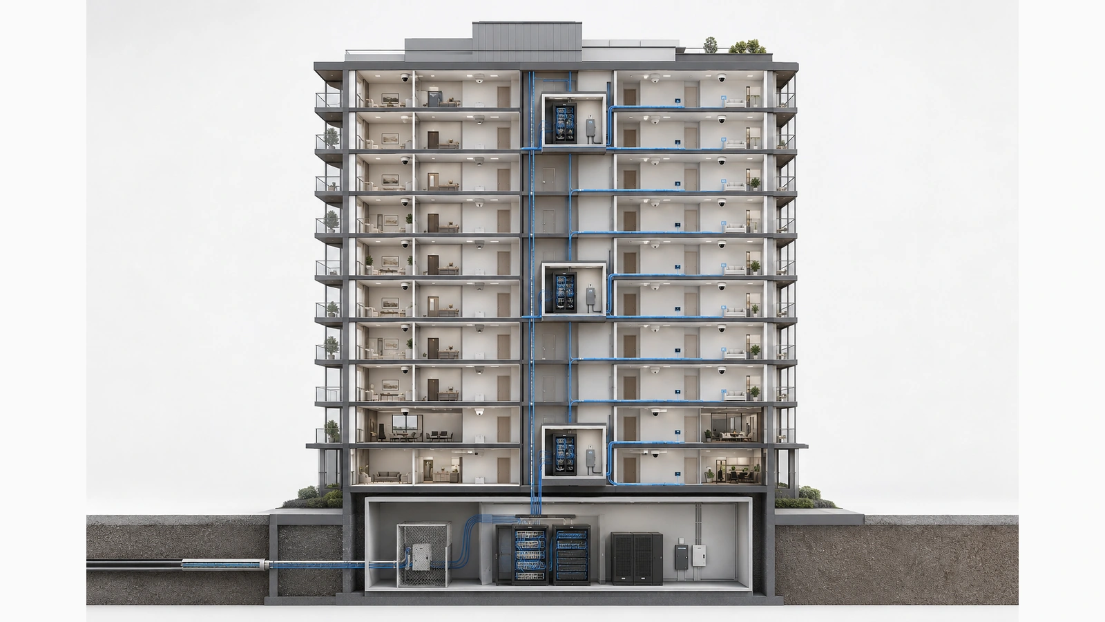
Designing network infrastructure for a high-rise building is not simply a matter of choosing switches, installing fiber, and adding Wi-Fi access points. The design must coordinate physical pathways, service ownership, resident requirements, building operations, security boundaries, equipment-room conditions, and long-term maintenance.
A decision that looks economical during construction can become an expensive operational limitation once walls are closed, units are occupied, and access to risers becomes restricted. Conversely, a well-planned foundation can support different providers, technologies, and service models without forcing the property to rebuild its physical infrastructure every time requirements change.
This guide presents a practical framework for designing that foundation. For a broader explanation of how the individual layers connect, begin with How High-Rise Network Infrastructure Works.
Key Takeaway
Successful high-rise network design begins with service requirements, ownership boundaries, pathways, and operational responsibilities—not an equipment list. The physical infrastructure should remain useful even as providers, electronics, and resident expectations change.
01 Define What the Building Is Actually Providing
Before developing a topology, the project team must define which services belong to the building and which remain the responsibility of outside providers or individual residents.
A condominium in which every resident orders private internet service has a different technical and operational model from an apartment building that includes managed connectivity with every lease. A mixed-use tower, senior living property, hospitality-style residence, or building with extensive smart-property systems introduces additional requirements.
The design team should identify every service expected to use the communications infrastructure, including:
- Resident internet or unit delivery pathways
- Common-area and amenity Wi-Fi
- Property-management and staff networks
- Video surveillance
- Access control and intercom systems
- Building automation and environmental controls
- Parking, gate, elevator, and package-management systems
- Cellular, public-safety, or other specialized communications systems
- Third-party vendor equipment and remote support connections
These systems do not automatically belong on one shared network. They may use common pathways or rooms while requiring separate ownership, security, support, and availability policies.
02 Establish Ownership and Demarcation Boundaries
Every major network component should have a clearly defined owner. That includes the carrier entrance, fiber backbone, copper cabling, racks, switches, wireless equipment, firewalls, battery systems, monitoring platforms, and unit-facing equipment.
Ownership is not merely a financial issue. It determines who may make changes, who receives alarms, who responds to outages, who maintains documentation, and who replaces failed equipment.
The carrier demarcation point also needs to be distinguished from the building’s internal distribution system. An internet service provider may deliver service into the property without accepting responsibility for the building-owned riser, floor switches, common-area Wi-Fi, or resident-support experience.
In buildings with multiple providers, the design should document how each provider enters the property, where its responsibility ends, which pathways it may use, and how technicians obtain authorized access.
Questions to Resolve Before Design Approval
- Who owns the backbone and horizontal cabling?
- Who operates resident-facing services?
- Who supports common-area and building-system networks?
- Where does each provider’s responsibility begin and end?
- Who approves vendor access and configuration changes?
- Who maintains drawings, port records, credentials, and warranties?
03 Survey Pathways Before Choosing the Topology
The most elegant logical design is of little value if the building cannot physically support it. A site survey should identify telecommunications rooms, risers, conduits, sleeves, trays, ceiling routes, fire-rated penetrations, and practical routes into units and common areas.
In an existing tower, pathways may be congested, undocumented, shared with unrelated systems, or inaccessible without entering occupied spaces. New construction offers more flexibility, but coordination must happen early enough to reserve appropriate rooms and routes.
The survey should also document:
- Available pathway capacity and anticipated expansion space
- Maximum practical cable distances
- Firestopping and code-compliance requirements
- Exposure to water, heat, humidity, dust, or physical damage
- Restrictions on technician access
- Vertical alignment between telecommunications spaces
- Potential conflicts with electrical and mechanical infrastructure
Spare conduit, innerduct, fiber strands, rack space, and properly sealed sleeves are often more valuable than installing oversized active equipment. Passive infrastructure is disruptive to add later; electronics are comparatively easy to replace.
04 Design the MDF and IDF Strategy
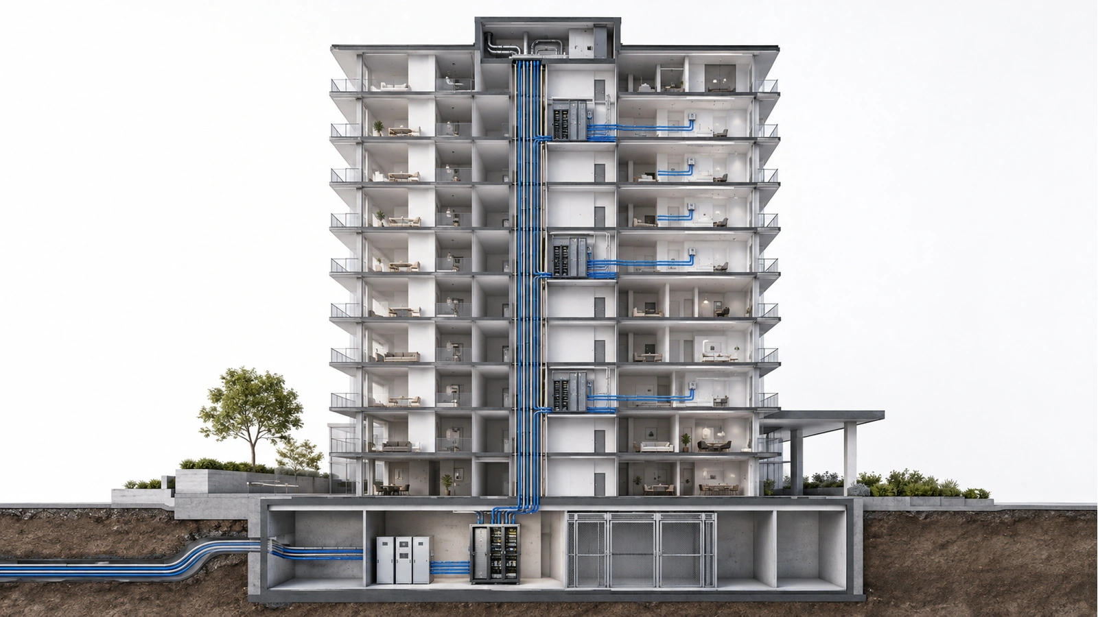
The main distribution frame, or MDF, commonly serves as the principal telecommunications room for carrier handoffs, core distribution, security appliances, and building-wide interconnections. Intermediate distribution frames, or IDFs, extend services to floors or groups of floors.
However, there is no universal requirement for one IDF on every floor or for every connection to return directly to the MDF. Room quantity and placement should be based on pathway availability, copper-distance limitations, floor layout, endpoint density, redundancy objectives, equipment ownership, and service access.
A centralized design may centralize administration and policy while still switching appropriate traffic elsewhere in the architecture. Likewise, a distributed design may reduce horizontal cable distances without sacrificing centralized visibility.
| Design Area | Questions to Resolve | Common Consequence if Overlooked |
|---|---|---|
| Location | Can pathways reach endpoints within technical and practical limits? | Excessive cable runs, added rooms, or difficult retrofits |
| Space | Is there room for racks, working clearance, patching, growth, and multiple owners? | Unsafe servicing and disorganized equipment expansion |
| Power | Are circuits, grounding, surge protection, and backup requirements defined? | Instability or outages despite healthy network equipment |
| Environment | Are temperature, humidity, ventilation, leakage, and dust controlled? | Shortened equipment life and intermittent failures |
| Security | Who can enter, and are access events documented? | Unauthorized changes and unclear accountability |
| Serviceability | Can technicians safely identify, test, and replace components? | Longer outages and higher maintenance costs |
Telecommunications rooms should not be treated as convenient storage. They need controlled access, suitable environmental conditions, organized grounding and power, durable labeling, and enough clearance for safe maintenance.
05 Select the Building Distribution Architecture
Once the service model and pathways are understood, the team can select the physical and logical distribution architecture. Common approaches include fiber from the MDF to floor-level IDFs, fiber deeper into each unit, centralized optical distribution, or hybrid designs combining fiber backbone capacity with local copper connections.
Fiber is generally well suited to vertical distribution because it supports long distances, provides substantial upgrade flexibility, and avoids the electrical characteristics of copper between building areas. Copper remains useful for shorter endpoint connections, especially where Ethernet and Power over Ethernet are required.
Fiber-to-the-unit can reduce reliance on active floor equipment and provide a flexible unit demarcation. Floor-based switching with copper to nearby units or building devices can simplify certain endpoint and power-delivery requirements. Neither method is universally correct.
The right choice depends on:
- Whether the property or a service provider owns the unit connection
- Existing pathways and available telecommunications spaces
- Unit distances and floor geometry
- Power and cooling availability in IDFs
- Desired provider flexibility
- Endpoint bandwidth and power requirements
- Maintenance responsibilities and technician access
The next articles in this category examine these decisions more closely, including network topology in multi-dwelling units and fiber distribution inside multi-dwelling buildings.
06 Separate Services According to Risk and Responsibility
Physical infrastructure may be shared without placing every service in the same trust domain. Resident access, property operations, surveillance, access control, guest Wi-Fi, building automation, and vendor-managed systems should be assessed separately.
Segmentation may use VLANs, virtual routing instances, firewall policy, private VLAN functions, identity-based access controls, provider platforms, or physically separate equipment. The appropriate method depends on scale, ownership, operational maturity, and risk.
Tenant isolation is also more nuanced than assigning one VLAN to every unit. That approach may work in some environments, but larger deployments may need scalable authentication, automated provisioning, private client isolation, or a managed service platform.
Segmentation should answer four practical questions:
- Which systems may communicate with one another?
- Which systems may reach the internet?
- Who is allowed to administer each environment?
- What happens when a device, vendor, or resident account is compromised?
Design Principle: Shared Infrastructure Does Not Require Shared Trust
A building can use common fiber, rooms, racks, or switching platforms while maintaining distinct security and administrative boundaries. Those boundaries must be designed, documented, and tested rather than assumed.
07 Build Wireless Coverage on the Wired Foundation
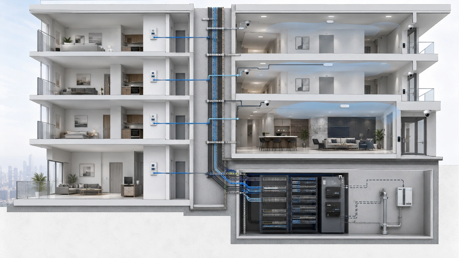
Wi-Fi planning should begin only after service ownership, wired distribution, and coverage objectives are defined. The correct design for resident units can be very different from the design for corridors, lobbies, pools, parking areas, offices, and amenity spaces.
Concrete walls, metal assemblies, fire-rated construction, reflective surfaces, stacked neighboring networks, and changing unit layouts can all affect radio behavior. High transmit power is not a substitute for appropriate access-point placement and channel planning.
Hallway access points are not inherently right or wrong. They may serve certain corridors and common areas effectively, but delivering reliable service inside units from hallway-mounted equipment depends heavily on construction, unit depth, door materials, frequency band, and service expectations.
Similarly, resident-owned consumer routers can be entirely appropriate when each unit has an independent internet service and the building is not promising managed unit-wide Wi-Fi. The challenge is coordinating a dense radio environment—not declaring every consumer device unsuitable.
Where the property provides managed Wi-Fi, the design must also address onboarding, tenant separation, roaming, support, monitoring, replacement cycles, and the boundary between building and resident devices. See the dedicated in-building Wi-Fi strategy guide for a deeper treatment.
08 Design Resilience Around Complete Service Paths
Redundancy is meaningful only when it protects the dependencies that can interrupt a service. Two core switches do not create a resilient system if both depend on one circuit, one fiber route, one room, one cooling system, or one upstream provider handoff.
For each important service, trace the complete path:
- Carrier or upstream service
- Building entrance and demarcation
- MDF equipment and power
- Vertical pathway and backbone
- IDF equipment and local power
- Horizontal cabling
- Endpoint, controller, cloud platform, or authentication service
The level of resilience should correspond to the service’s operational importance. Resident convenience Wi-Fi, property-management connectivity, door access, and life-safety-related communications may require different continuity strategies.
Backup power must also be sized around the desired operating time and the actual load. Batteries require monitoring, maintenance, and eventual replacement. A generator-backed electrical circuit is useful only when the relevant network equipment and upstream dependencies remain available.
Network infrastructure serving fire alarm, emergency communications, public-safety radio, elevators, or other regulated systems must be coordinated with qualified specialists and the applicable authorities. General data-network guidance should never substitute for code-specific engineering.
09 Document, Test, and Prepare for Operations
A high-rise network is not complete when the equipment powers on. The building needs records that allow another qualified technician to understand the system without reverse-engineering it during an outage.
The final documentation package should include:
Pre-Handover Infrastructure Checklist
- Current logical and physical network diagrams
- MDF, IDF, riser, and pathway drawings
- Rack elevations and equipment inventories
- Fiber-strand, patch-panel, port, and cable schedules
- Demarcation and ownership records
- IP addressing, segmentation, and administrative boundaries
- Power, UPS, grounding, and environmental requirements
- Test results for installed copper and fiber cabling
- Configuration backups and secure credential-transfer procedures
- Warranty, licensing, monitoring, and support information
- Approved vendor-access and escalation procedures
- A documented process for future changes
Testing should verify more than basic internet access. The team should validate backbone links, cabling certification, failover behavior where provided, segmentation policies, wireless coverage objectives, monitoring alerts, backup power behavior, and access to management systems.
The design should also make future change manageable. Spare passive capacity, modular racks, clear labeling, accessible pathways, documented policies, and vendor-neutral cabling give the property options without requiring it to predict a specific technology timeline.
High-rise infrastructure succeeds when it can be operated as clearly as it was designed. A strong backbone is important, but long-term performance also depends on defined ownership, secure service boundaries, maintainable rooms, complete documentation, and realistic support procedures.
The next step is to determine how these design decisions translate into a specific physical and logical layout. Continue with Understanding Network Topology in Multi-Dwelling Units.