
Introduction
“How many access points do I need?” sounds like a question that should have a simple numerical answer. Divide the home’s square footage by the advertised coverage of one access point, round up, and purchase that many units.
Unfortunately, buildings do not behave like open mathematical grids. A 4,000-square-foot single-story home with an open interior may be easier to cover than a 3,000-square-foot property divided across two floors with masonry, mechanical spaces, mirrors, and separate wings.
The correct number of access points depends on where dependable Wi-Fi is required, what the signal must pass through, how the property is shaped, how the access points will connect to the network, and how people use the wireless system. Square footage provides context, but it cannot produce the final answer by itself.
01 Why Square Footage Cannot Answer the Question Alone
Access-point coverage is shaped by the environment around it. The same access point can perform very differently in two homes of equal size.
The most influential variables include:
- The number of floors
- The length and shape of the floor plan
- Drywall, concrete, masonry, tile, metal, glass, and other materials
- The access point’s mounting position and intended orientation
- The required frequency bands and performance level
- Neighboring wireless networks and other interference
- The location and behavior of client devices
- Indoor, outdoor, garage, and detached-building requirements
Manufacturer coverage figures are useful for comparing product positioning, but they should not be treated as promises for a finished home. They cannot account for the exact obstacles, room arrangement, interference, or service expectations of a specific property.
The practical objective is also more demanding than making a network name appear on a phone. A weak signal may allow a device to remain connected while producing slow responses, unstable video calls, interrupted Wi-Fi calling, or inconsistent smart-device operation.
The design should therefore target usable signal quality and predictable performance in important areas—not the largest possible coverage circle on paper.
02 Understand Coverage and Capacity as Separate Needs
Access points are added for two primary reasons: to extend usable coverage or to distribute wireless demand. Those reasons can lead to different designs.
Coverage-driven design addresses areas where distance, walls, floors, or the building’s shape weaken the connection. A long bedroom wing or an outdoor patio may need another access point even if relatively few devices use that area.
Capacity-driven design addresses areas where many devices or demanding applications share the same wireless environment. A large open entertaining space, busy home office, or media area may have excellent signal but still benefit from a carefully planned additional radio when usage is unusually concentrated.
Device count alone is not enough to determine capacity. Fifty low-traffic smart sensors do not create the same demand as several computers transferring large files, multiple high-resolution streams, active video conferences, and wireless security cameras operating simultaneously.
Likewise, one person working through a VPN does not automatically require a dedicated access point. What matters is the total traffic pattern, required consistency, available channels, client capabilities, and the quality of the existing wireless connection.
03 Divide the Home Into Logical Coverage Zones
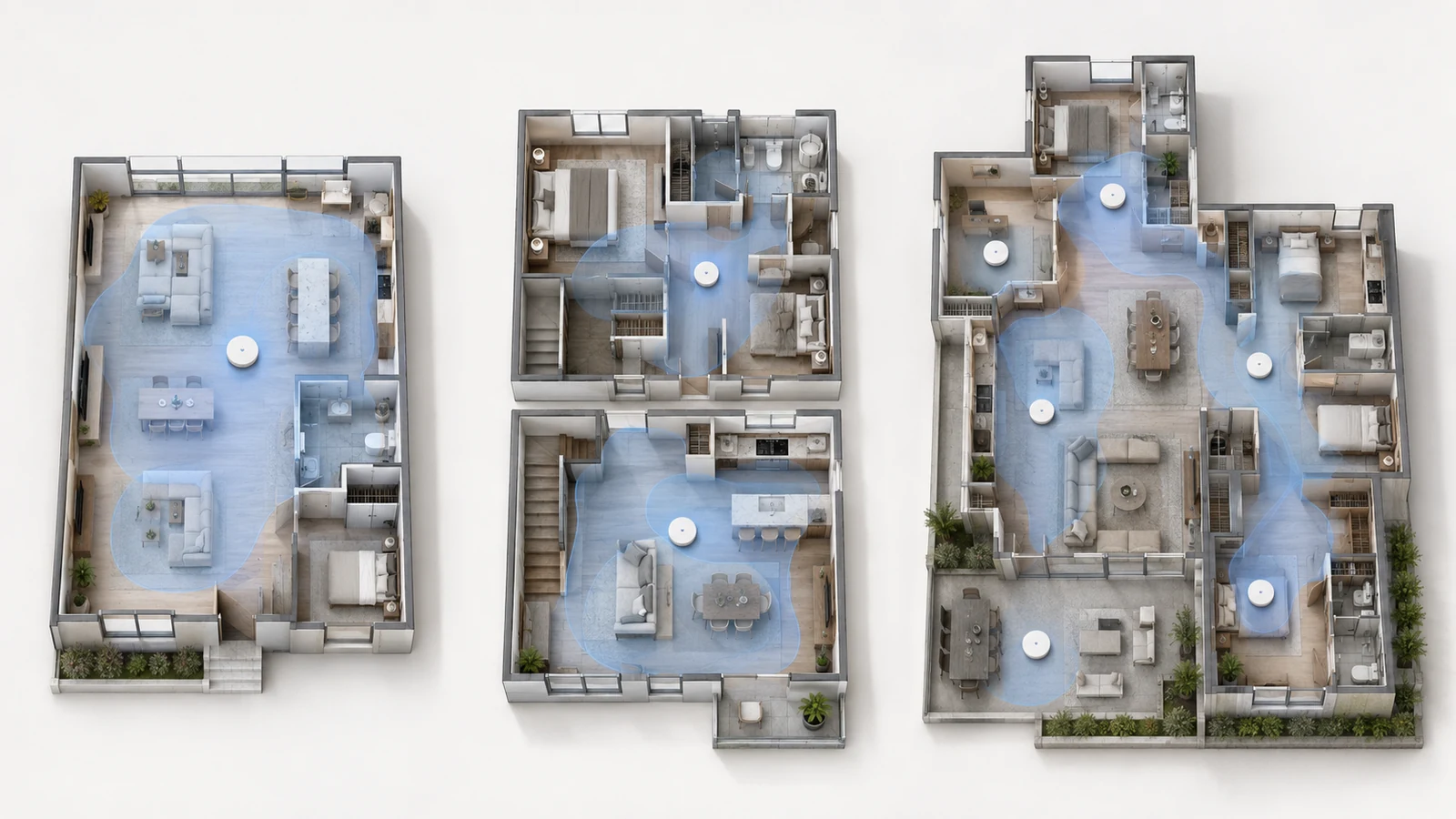
A more useful estimating method begins by dividing the property into areas that can reasonably be served from well-positioned access points.
Typical coverage zones might include:
- The main kitchen and living area
- A downstairs bedroom or office wing
- An upstairs bedroom and hallway area
- A media room or separate family room
- A garage or workshop
- A covered lanai, pool deck, or outdoor kitchen
- A detached guesthouse or other separate structure
One access point may serve more than one adjacent zone when the layout is open and the materials are favorable. Conversely, one apparent zone may need to be divided when dense barriers separate the rooms within it.
Start by marking the areas where Wi-Fi is essential, helpful, or unnecessary. A home office used throughout the workday deserves a different priority than a storage room where an occasional signal is sufficient. This prevents the design from treating every square foot as though it has identical value.
For a broader view of how these zones fit into the complete gateway, switching, and cabling architecture, see the best Wi-Fi setup for large homes.
04 Adjust the Estimate for Construction and Layout
After identifying the initial zones, examine what separates them. Wireless signals do not pass through every material equally, and multiple moderate obstacles can be as important as one obvious barrier.
Potentially difficult conditions include:
- Concrete or masonry walls
- Metal framing, cabinets, or equipment enclosures
- Stone fireplaces and large tiled surfaces
- Elevator shafts and mechanical rooms
- Mirrors, large appliances, and expansive glass assemblies
- Foil-backed insulation or radiant-barrier materials
- Dense floor assemblies between stories
This is particularly relevant in Naples and other Florida markets. Concrete block is common around the building envelope, and indoor access points may have difficulty serving patios, driveways, cameras, or pool areas through exterior walls and impact-resistant assemblies.
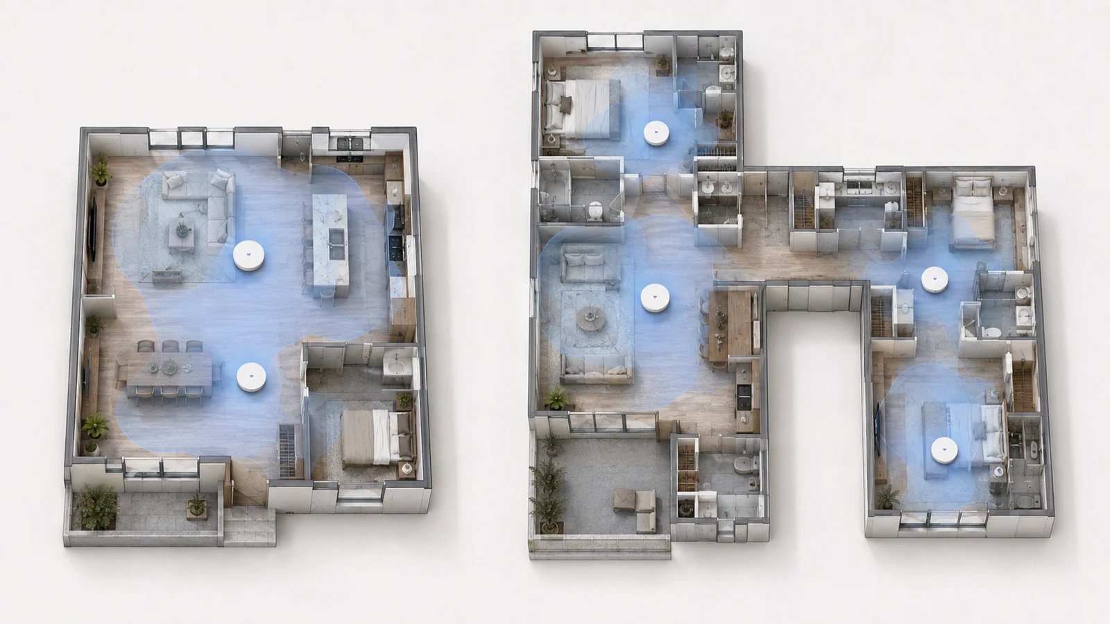
Layout shape also matters. Long ranch homes, L-shaped plans, U-shaped properties, attached additions, and separated wings stretch coverage in ways that a simple total-area calculation cannot capture. Increasing transmit power at one end of the house does not create an equally strong return path from a phone at the other end.
When a wall or floor is likely to become a meaningful boundary, place an access point on the side where dependable service is required rather than expecting one radio to overcome every obstruction.
05 Use Square Footage Only as an Initial Planning Range
Although square footage cannot determine the final count, it can establish a preliminary range for conventional residential planning. The ranges below assume appropriately selected access points, sensible mounting positions, Ethernet backhaul where practical, and ordinary residential usage.
| Approximate Home Size | Preliminary Indoor Range | Conditions That May Change It |
|---|---|---|
| Up to 2,000 sq ft | Often one or two access points | Multiple floors, dense walls, poor central placement, or separate outdoor requirements may justify a second or additional zone |
| 2,000–3,000 sq ft | Often two access points | An open single-story plan may need less; divided floors, long layouts, or high-priority rooms may need more |
| 3,000–4,000 sq ft | Often two or three access points | Floor arrangement, bedroom wings, concrete construction, and outdoor living areas become increasingly important |
| 4,000–6,000 sq ft | Often three or four access points | Complex estates, multiple wings, dense materials, concentrated usage, or extensive exterior spaces may require additional zones |
| Over 6,000 sq ft | Floor-plan design required | Guest buildings, large outdoor areas, unusual construction, automation, security, and operational needs make simple size estimates unreliable |
These figures are starting assumptions, not minimums, guarantees, or purchase recommendations. A properly positioned two-access-point design can outperform a poorly positioned four-access-point installation. The count should remain flexible until mounting locations and building conditions are considered.
Outdoor access points should generally be evaluated separately from the indoor estimate. A property may have complete indoor coverage and still require another access point for a lanai, pool, dock, driveway, or detached space.
06 Plan Multi-Floor Homes as One Building
A common shortcut is to assign one access point to each floor. That may be appropriate in a small, open two-story home, but it is not a universal professional baseline.
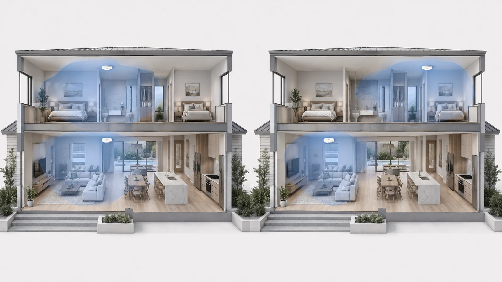
Each floor must be evaluated according to its own shape and rooms while also accounting for coverage that travels vertically. An access point on one floor may contribute useful service above or below it, but floor assemblies, ductwork, plumbing, tile, and mounting orientation can make that coverage uneven.
Access points should not automatically be installed directly above one another. Stacking them can concentrate overlapping coverage in one part of the property while leaving another section underserved. Staggered positions often distribute service more effectively across a multi-floor plan.
For example, a two-story home might use:
- A downstairs access point near the kitchen and main living area
- A second downstairs or in-wall unit serving an office and guest wing
- An upstairs access point serving bedrooms and the hallway
Another home of the same size may need two upstairs units and only one downstairs. The floor plan—not symmetry—should decide.
07 Avoid Solving Every Weak Area With Another Access Point
More access points do not automatically create better Wi-Fi. Every additional radio participates in the same limited wireless environment and must be coordinated with the rest of the system.
Overdeployment can contribute to:
- Unnecessary channel reuse and interference
- Excessive coverage overlap
- Client devices remaining connected to a less suitable access point
- More complicated channel and transmit-power planning
- Additional switching, cabling, PoE, licensing, and maintenance costs
Before adding another access point, ask whether the existing one is poorly positioned, enclosed, mounted in the wrong orientation, operating at an unsuitable power level, or using a congested channel. Correcting the design may improve the weak area without increasing the hardware count.
The opposite mistake is trying to cover too much area from too few access points by maximizing transmit power. A phone or smart device may hear the access point while lacking enough transmit capability to communicate back reliably. Strong transmission from the network does not correct an unbalanced two-way connection.
The objective is controlled coverage with enough overlap to support movement between service areas—not maximum signal from every access point in every room.
08 Backhaul and Placement Can Change the Required Count
An access point can only serve its intended zone effectively when it has a reliable path back to the network. Ethernet backhaul normally provides the greatest placement freedom because the access point can be installed where coverage is needed without also maintaining a strong wireless link to another node.
Wireless mesh nodes must be close enough to their upstream node to receive a dependable backhaul signal. Placing a mesh unit inside an existing dead zone does not solve the underlying problem; the node begins with the same weak connection it is expected to extend.
In some homes, that limitation leads to additional mesh nodes used primarily to bridge distance rather than serve distinct client zones. This can make the hardware count look higher than a comparable wired design. The differences are explained in Wi-Fi mesh versus wired backhaul.
Mounting position is equally important. Ceiling-mounted, wall-mounted, desktop, and in-wall access points may have different intended coverage patterns. A technically excellent device installed inside a cabinet, behind a television, near dense mechanical equipment, or at the far edge of its intended zone may perform worse than a modest unit placed correctly.
Before increasing the estimated quantity, refine the likely locations using the detailed guide to how to place access points throughout a home.
09 Final Access-Point Estimation Framework
Access-Point Count Planning Checklist
- Obtain or sketch a floor plan for every level of the property.
- Mark essential indoor, outdoor, garage, and detached-building coverage areas.
- Identify the main living zones, bedroom wings, offices, and media spaces.
- Note concrete, masonry, metal, mirrors, mechanical areas, and dense floor assemblies.
- Estimate an initial count using coverage zones and square footage only as starting references.
- Adjust the estimate for long, L-shaped, U-shaped, or separated layouts.
- Evaluate outdoor areas separately from the indoor access-point count.
- Consider capacity where demanding wireless use is concentrated.
- Select realistic mounting positions and intended access-point orientation.
- Confirm Ethernet or dependable mesh backhaul at every proposed location.
- Check for excessive overlap before adding another access point.
- Validate important rooms and roaming paths after installation.
There is no professional rule stating that every home needs one access point per floor, one per fixed number of square feet, or one for every certain number of devices. Those shortcuts ignore the building and the people using it.
For many homes, the correct answer will fall within a modest range. The difference between a successful design and an unreliable one is usually not whether the estimate began at two, three, or four access points. It is whether those access points were assigned clear coverage responsibilities and installed where they could fulfill them.
Begin with zones. Adjust for construction and shape. Separate indoor and outdoor requirements. Confirm the backhaul. Then validate the result in the locations where dependable Wi-Fi actually matters.